The Growing Demand for Energy
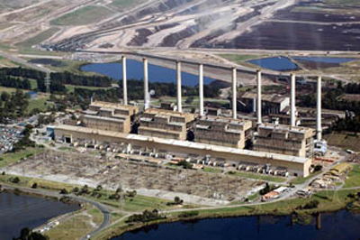
Built between 1964 and 1971, the Hazelwood Power Station in Victoria’s Latrobe Valley originally planned to have six units producing 200 MW each. However, growing electricity demand in the late 60s prompted the approval of a proposal to add two units to the station to increase generating capacity. The eight-unit power station was producing 1,600 MW output by the early 70s; each unit generated 200 MW of power. In recent years, this power station has moved to improve its output through thermal efficiency gains and increasing each unit’s capacity by 20 MW.
Engineered Modifications to Improve Pump Efficiency
Having modified the turbines to use less power, the plant needed to upgrade the 11-stage ring section, boiler feed pumps to meet the newly elevated performance requirements. International Power Hazelwood (IPRH) contacted a pump aftermarket service centre in the Latrobe Valley to determine if modifications could be made to seven of these pumps within a two-year time period.
Though the original pump curves implied that the pump would have sufficient head and flow to handle the increased service conditions, several factors were discovered during an inspection that would determine the course of action. Due to a vane pass vibration, the diffuser vanes had been machined to correct a vane pass issue that the pump experienced early on in its life. As a result, the hydraulic performance of the diffuser was compromised, and the pump no longer matched the manufacturer’s original design. The motor size also limited power usage.

Rotor Centralization was performed to improve pump efficiency
At a minimum, IPRH required that the pump be returned to the original design duty. Taking this into account, the aftermarket service centre proposed several modifications to the pump that would ensure it would not only meet performance requirements but also demonstrate improved efficiency and energy savings.
Once the plant approved the proposed modifications and upgrades, the service centre evaluated the impeller and diffuser hydraulic design data. Due to an existing thick exit impeller vane tip, the exit area of the impeller could be increased. The underfilling calculations were then verified using an underfilling program to confirm the intended flow increase through the pump. Proper underfilling of the impeller would alter the pump curve to achieve the new duty point.
The service centre reduced the A-Gap and corrected the overlap to improve flow through the pump and reduce recirculation. However, to perform the A-Gap modification, the impellers needed to be completely re-welded, stress relieved and re-machined. After the welding and machining were completed, all the waterways on the diffusers and impellers were highly polished to reduce friction and gain as many efficiency points as possible.


The impellers were completely re-welded and polished (before, top, and after, bottom)
The centre performed rotor centralization, which involves the centring of the rotating hydraulic components (impellers) within the stationary hydraulic components (in this case, the diffusers) to optimize pump efficiency. Pump efficiency is improved because a rotor with aligned hydraulic components is less likely to experience turbulence and heat rise in the fluid as it exits the impeller and enters the diffuser. This also helps in reducing the overall vibration signature. The service centre performed a detailed dimensional analysis, using a computerized coordinate measuring machine, to take numerous dimensions of each hydraulic component at every stage to ensure centerline compatibility.
Replacing metal stationary wear components with composite materials also provided an opportunity to significantly reduce running clearances, which further improves efficiency. Using polymer or graphite composites, running clearances can typically be reduced by 50 percent. Equal or improved flow can be achieved with less horsepower. Using less power lowers operating costs and burns less fuel. Having a thorough understanding of the benefits of using composite materials, the aftermarket centre changed the wear ring material from austenitic cast iron to a continuous carbon-fibre composite plastic.

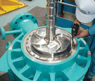
Pump being assembled
Assembling, Installing and Testing the Rebuilt Pump
Due to the significant reduction in running clearances, much care was required in the assembly of the pump. All fits were tightened and faces were machined to ensure trueness. Step by step measurements were taken during the assembly process to ensure alignments were correct. Lifts and floats were also carefully checked.
The rebuilt pump was returned to the power station, and the plant’s own condition monitoring group conducted a performance test after it was installed. The performance test revealed a generous rise in performance, proving an increase in flow of 7.8 percent above that of the original specified maximum duty point for this pump. IPRH was pleased with the results-not only was the efficiency increased substantially, but the amount of energy used to run the pump also decreased. This reduction of energy used to run the pump provided a direct savings to the station.

Hazelwood power station
Lessons Learned
While governments and the power generation industry face the current challenge of providing enough energy for a booming world population, one of the most important lessons we can learn from this example is that a power station can manage their carbon footprint by reducing the amount of energy used by their pumping systems. According to Pump Life Cycle Costs: A Guide to LCC Analysis for Pumping Systems by the Hydraulic Institute and Europump, pumping systems consume about 20 percent of the world’s energy and 20 to 50 percent of the energy in some industrial plants.
In this instance, a pump that was more than 40 years old was able to be re-engineered at significant cost savings and higher generation capacity.
Service providers overall should not only understand the available engineered upgrades but should also properly perform the modifications and return a more efficient pump.
About the Authors
Ross Bertoli is general manager of Hydro Australia, 011-61-3-5165-0390. Mark Moerke is turbine section manager with International Power Hazelwood.
http://www.pump-zone.com/pumps/centrifugal-pumps/improving-pump-efficiency-to-sa…
